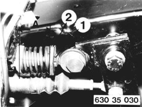
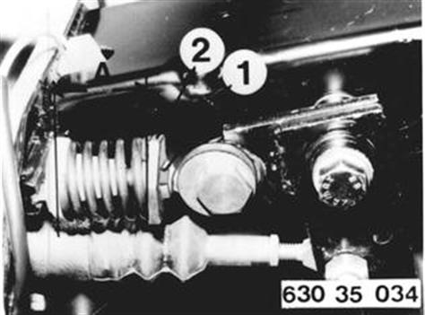
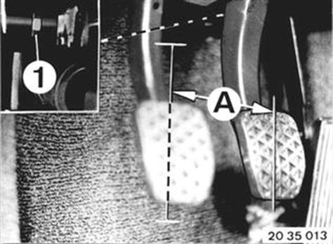
REMOVING AND INSTALLING CLUTCH PEDAL Detach and attach instrument panel trim at bottom left 51 45 180. Unscrew lovknut (1) and relax TDC spring with nut (2). Installation: Adjust TDC spring in installed and engaged state. Distance A¹).  51 45 180 ¹) See Specifications 51 45 180 ¹) See Specifications
|  |
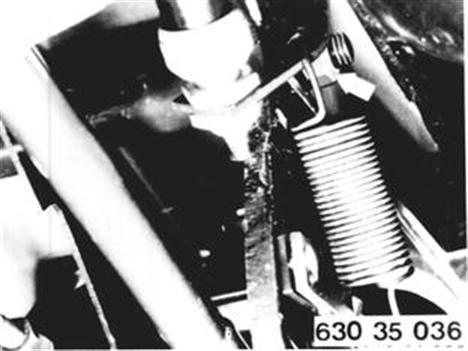
Detach piston rods. Installation: Tightening torque¹). Replace self-locking nuts. ¹) See Specifications
|  |
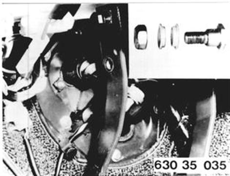
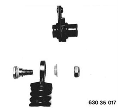
Remove setscrew. Installation: Note sequence of installation. Check sleeves for wear, replacing if necessary and lubricating with lubricant¹). ¹) See Specifications
|  |
Unscrew stop nut and remove bearing screw. Installation: Tightening torque¹). Replace self-locking nuts. ¹) See Specifications
|  |
When Replacing: Detach TDC spring at clutch pedal. Installation: Note sequence of installation. Check bushings for wear, replacing and lubricating¹) if necessary. Replace self-locking nuts. Tightening torque¹). ¹) See Specifications
|  |
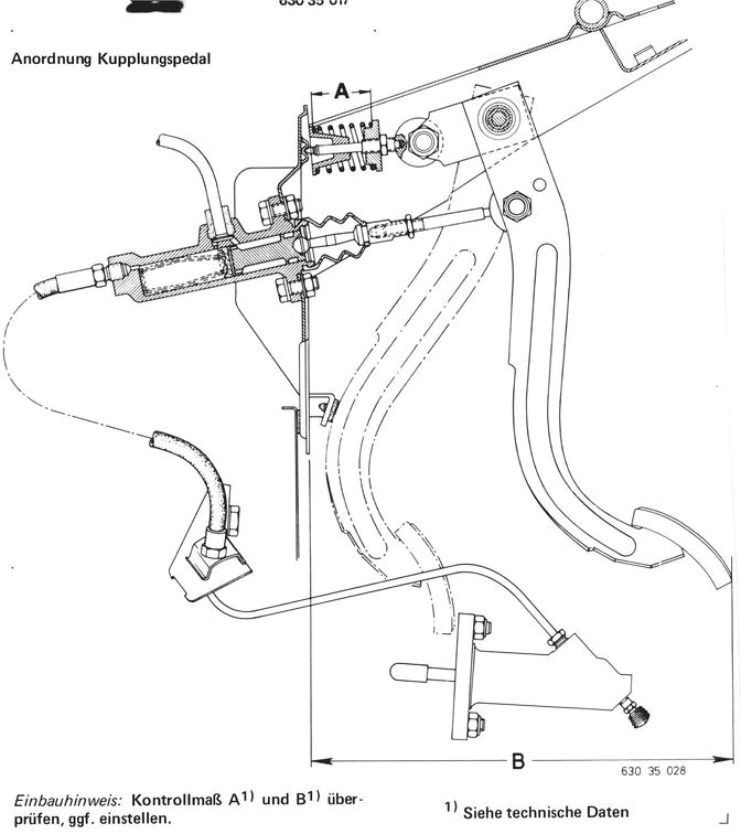
LAYOUT ASSEMBLY DRAWING OF CLUTCH PEDAL Installation: Check distances A¹) and B¹), correcting if necessary. ¹) See Specifications
|  |
Vehicles after change point in 1982 REMOVING AND INSTALLING CLUTCH PEDAL Remove and install instrument panel trim at bottom left. | 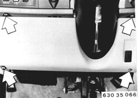 |
Disconnect brake pedal return spring. | 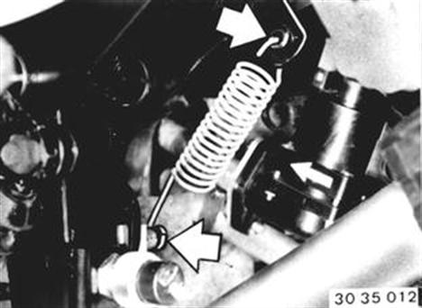 |
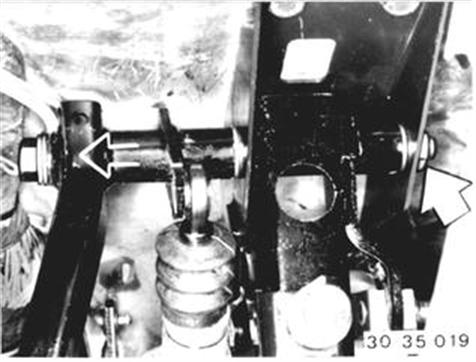
Press off clamp (1) on brake linkage. Pull out shaft (2). | 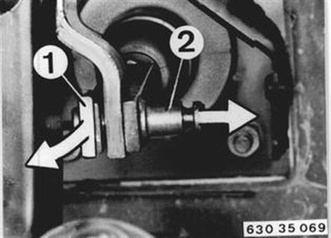 |
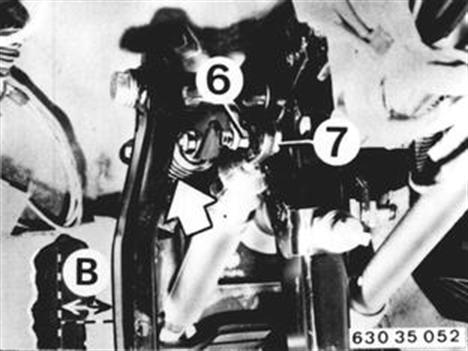
Unscrew nut (6). Pull out eccentric (7). Installation: Check installed position of over-center helper spring. Adjust clutch pedal height to distance (B)* with eccentric (7). Tightening torque*. * See Specifications
|  |
Unscrew nut. Pull out bolt. Remove pedal. Installation: Replace self-locking nut. Tightening torque*. * See Specifications
|  |
 |
|
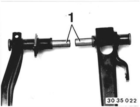
Installation: Adjust brake pedal height on brake linkage (1) - see brake pedal layout drawing - 35 41 001. Tightening torque*. 35 41 001 * See Specifications
|  |
Installation: Adjust stop light switch. B = 5 to 6 mm (0.197 to 0.236"). | 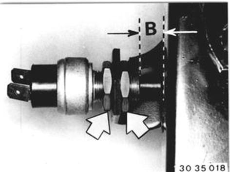 |